Stimulated Condensation Resonator Assembly
Contents
Base Preparation
- Staring from a used base...
- Apply a small drop of tetrahydrofuran (THF) through the back side of the
base chuck. Repeat every few minutes to weaken the glue.
- First expand the chuck 1/4 turn beyond contact with the expander screw,
then push out the disk/puck with the push-pin screw.
- Pry off the electrode plate.
- Soak the base in tetrahydrofuran for a few days to weaken the pin glue
joints.
- Press out the pins, and again soak the base and pins in THF for a few
days. Clean off all remnants of epoxy..
- Make sure that the pins slide easily through the holes.
- Check the fit of the puck into the clamp. The clamp screw should be turned
no more than necessary open the jaw for the puck, about 1/4 turn. The puck should
not be loose
with the clamp screw removed.
- Check the clearance in the jig when assembled without glue. Make, or check
the
gauge-wedge to test the actual assembly.
Electrode Preparation
- Bend the corners of the electrode plate slightly down, away from the
electrode face.
- Solder bare copper wires through the corner holes. Make sure both the top
and bottom cladding is soldered. Keep the solder below the plane of the
electrode face.
- Prepare the three glass lapping plates by rubbing them together with wet
600 SiC grit. Systematically cycle through the thee possible pairs, rinsing
and applying fresh grit each new pair.
- Lap the electrode face against the frosted glass plates. Apply only a soft
finger pressure to the center back of the electrode. Move in a circular motion
covering all of the glass lapping plate.
- When a plate becomes charged with copper dust, move to a new plate. After
all three have been charged, clean them by regrinding as in the previous step.
- Continue until the ground region on the electrode face spreads out to
covers the whole surface.
- Clean the electrode with a methanol dampened wipe. Make sure to clean the
bottom surface inside the pin holes.
Disk Polishing
- Measure the disk diameter on the Leitz Precision Boring Jig and dial
gauge.
- Assemble the disk to the polishing pin. Measure the height difference
between the disk and the pin body with the Olympus microscope.
- Shim the
pin to the center-line. and reassemble with a sesame-seed-sized bit of beeswax
in the center
- Set the wax by coving with Al foil an the small hot plate, melting and
cooling.
Polishing Pin and Mounting Jig
- Prepare 5x7 mm pads of leather. Attach one to the end of a popsicle stick
with double-sided-sticky tape.
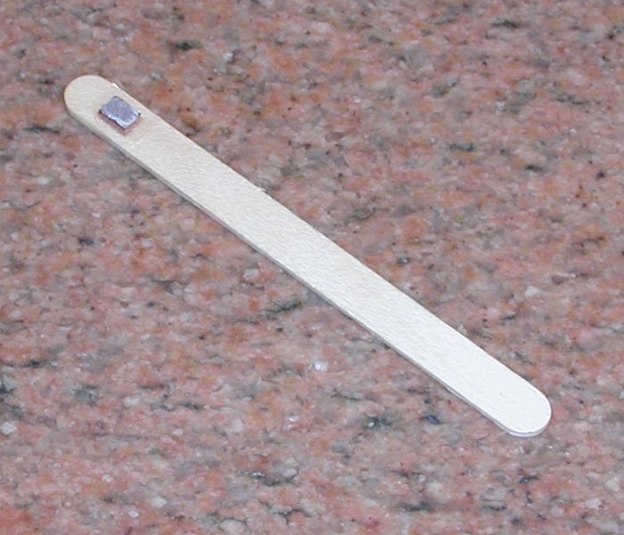
Polishing Stick
- Wet the pad with propylene glycol. Spread a poppy seed sized blob of
diamond powder around the pad.
- With the pin in the small lathe, press the pad against the disk,
continually moving around the pad's surface and changing the contact angle +/-
20 degrees. Press with approximately 10 g equivalent on the pad.
- Use fresh pads and grit after about 2 minutes of polishing, covering the
whole pad's surface.
- Use the 1500 grit until most of the pits are gone. This could take 6 to 12
pads.
- Move through the 8000, 14000, 50000, 100000 with 2-4 applications each.
Wash the disk with gushing tap water, very gently wiping with a frazzled Q-tip
to remove all traces of grit before moving to the next size.
- Heat the pin and remove the disk. Avoid scraping the disk across the end
of the pin -- there will likely be grit lodged in the beeswax.
- Clean the beeswax off with (napthalene), then methanol.
Disk/Puck Gluing
- Clean the puck-jig.
- Clean the disk and the puck of dust and oily residue. Finish with
methanol.
- Mount the disk in the puck-jig and adjust the positioning pins to center
the puck. Use the Leitz Precision Boring Jig with a dial gauge to measure the disk and
set the positioning pins.
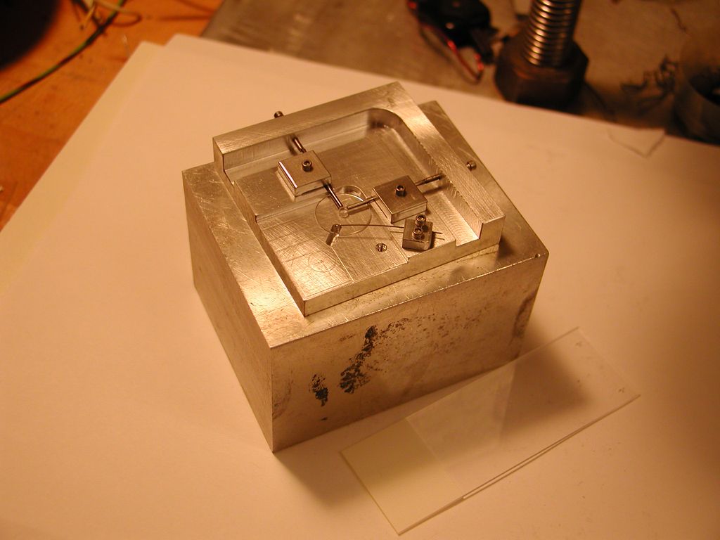
Gluing Jig
- Clean off the disk and puck one last time with the vacuum chuck.
- Mix Stycast 1266 and apply a spot using a 1 sec. perpendicular contact
with a glue filled 0.010 ID CuNi tube.
- Drop the puck into position with the vacuum chuck.
- Apply about 10 g weight equivalent to the puck making sure the puck is
contacting the positioning pins.
- When the glue is thick, but still flowing, remove the disk and inspect for
1) proper centering to +/- 50 microns; 2) No bubbles or particles in the
joint; and 3) uniform meniscus seen as a 10 - 100 micron ring around the puck.
- Bake for 24 hours at 100 C after curing.
Disk Evaporation
- Prepare a 6 cm long 3/32 dia. steel rod with one end tapered to about a
1.5 mm dia. flat tip.
- Set the disk/puck in the gluing jig and center it under the boring head of
the Leitz.
- Adjust the 3/32 chuck to minimize free-play of the rod, but allowing it to
slide out under gravity.
- Wet the end of the rod with a very small amount of glue. Hold it in place
in the jig bore with a
tensioned hook.
- Lower the head until the rod is about 5 mm above the disk, then lower the rod to the disk with tweezers
after removing the hook.
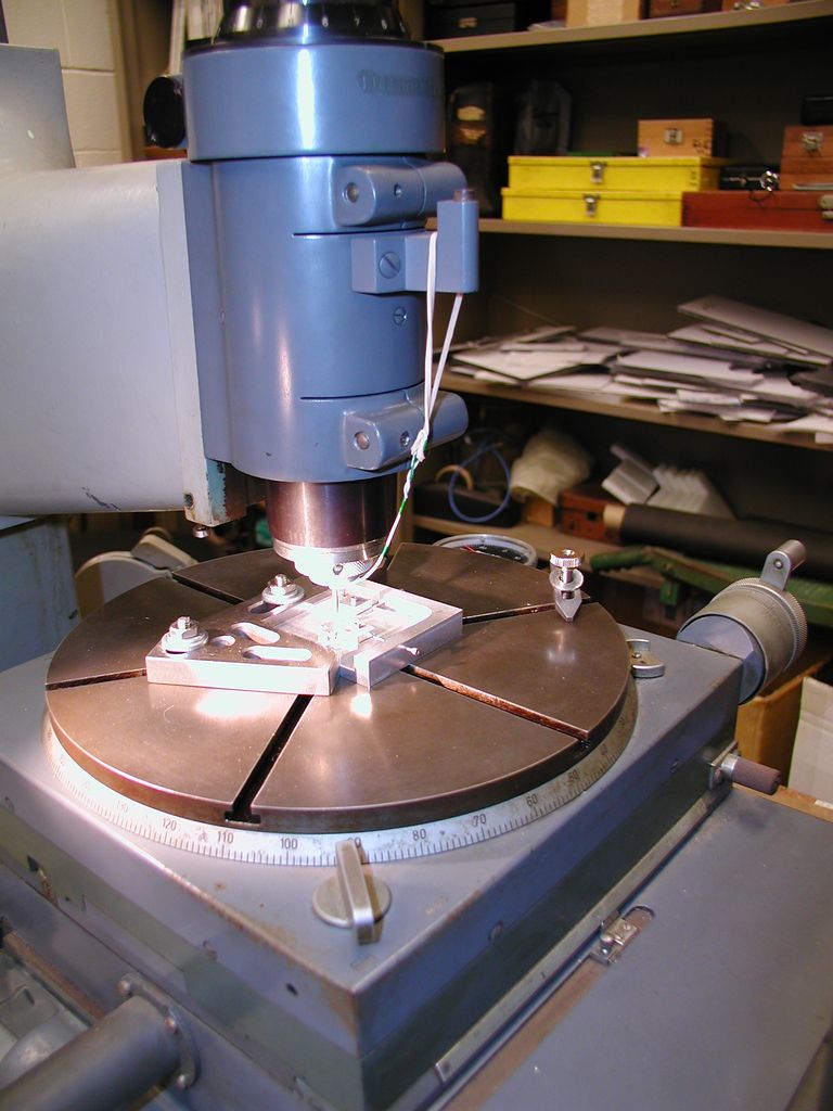
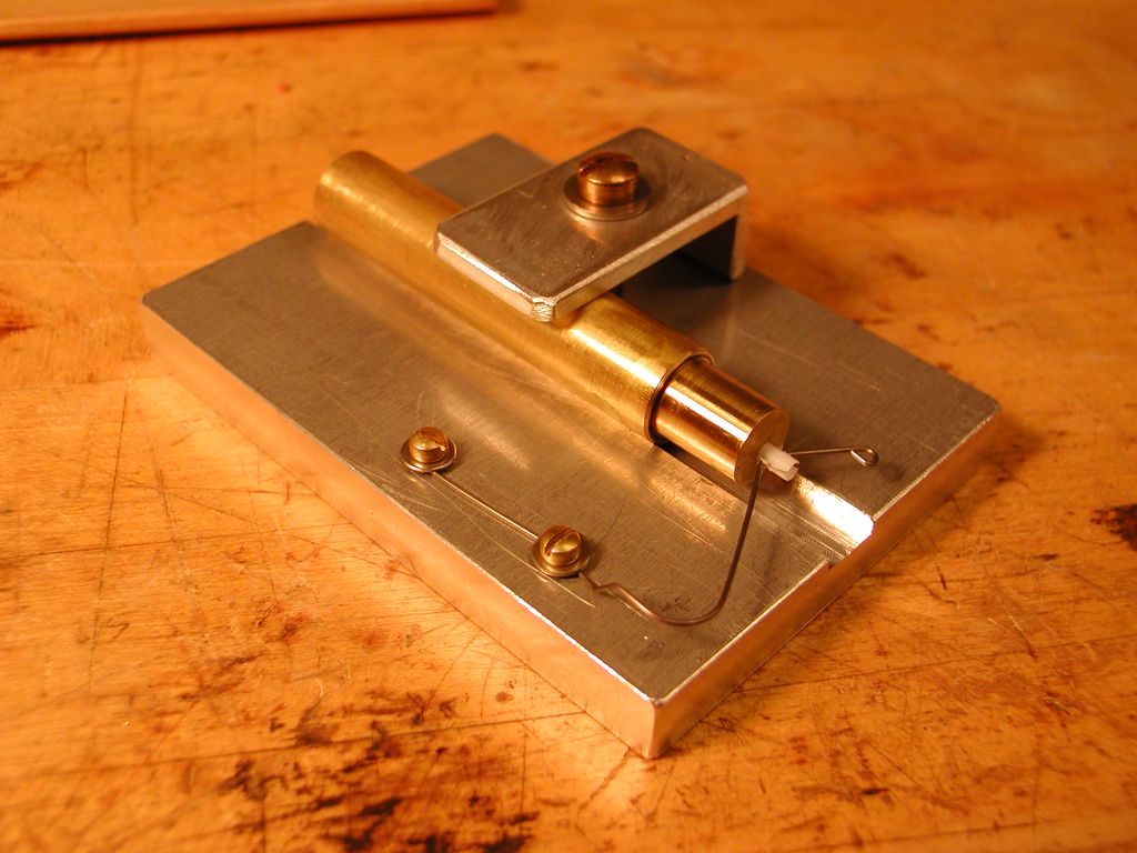
Leitz Precision
Boring Jig - Gluing the rotisserie rod.
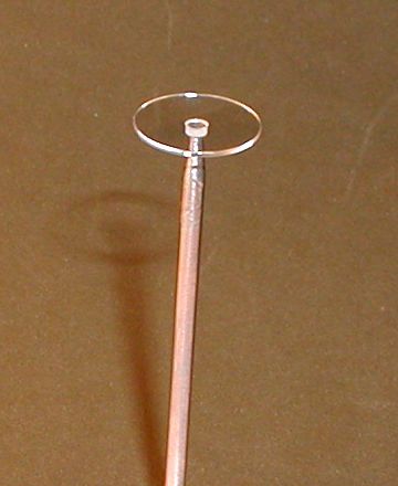
Disk glued on the rotisserie rod.
- After it is cured, move into the clean shroud. Inspect and clean the disk ion the rod.
- Transfer it to the evaporator and mount in the rotating holder.
- Arrange 3 Ag boats and a Ti wire at ~10 cm.
- Deposit 50 Angstroms of Ti then 2000 Angstroms each Ag.
Gap Spacing
- Inspect the disk for dust particles. The puck side is the most crucial
- Place the disk face down into the assembly jig on top of a paper cushion.
Snap off the rotisserie rod. Remove any remaining glue bits.
- Prepare four 15 mm x 2.5 mm spacer strips. They must be of matte-finish
HDPE sheet.
- Tape them to the alignment tabs, sticking 7.5 mm past the end.
- Place the tabs into the slots on the jig for about 3-4 mm intrusion of the
spacers into the disk surface. Keep the spacer tabs outside of the electrode
corners.
- Place the electrode plate into position above the spacers.
Post Gluing
- Attach the base to the top section of the assembly jig. Make sure that the
orientation is correct, and that the spreader screw is opening the clamp jaws
slightly - 1/4 turn beyond contact.
- Prepare a paste of Stycast 1266 and silver flake.
- Wet the inner edge of the base clamp with a small amount of the paste.
- Mate the alignment sockets of the two jig halves. Keeping pressure over
the alignment sockets, carefully lower the base so that the clamp mates with
the puck. Check for proper mating with the gauge wedge.
- Attach the pressuring screw/spring to keep things in place.
- Remove the spreader screw.
Pin Gluing
- Apply a small drop of pure (no silver) glue to the face of an electrode pin.
- Slide it into its hole in the back of the base plate, glue end toward the
electrode. Move rapidly to avoid allowing the glue to wick off onto the side
of the hole.
- After all four pins are in, apply a small drop of glue between the pins and their guide
holes -- just enough to fill the gaps and no more.
- Leave alone as the glue cures.
Capacitance Check
- Pull the spacer tabs with spacers out.
- Apply pressure to the jig alignment sockets,, remove the pressure screw,
and separate the jig halves.
- Check the capacitances with the HP vector impedance meter.