
Dilution Refrigerator
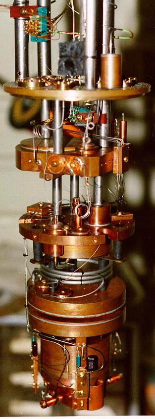
Below are pictures of the dilution refrigerator built at Wesleyan University. The schematic on the right shows the major components, generally getting colder from top to bottom. The whole unit is enclosed in a vacuum space for insulation and submerged in a bath of liquid helium at 4.2 K. Moving down the chain...
The 1K pot cools to about 1.4 K by pumping away the vapor pressure in the pot. The lower pressure coexists in equilibrium with liquid at a lower temperature. Liquid helium from the bath is drawn in at a limited rate through a flow restriction replacing the evaporated liquid. The cooling power is limited by the flow restriction and pumping rate. The base temperature is limited by the pumping efficiency as the vapor pressure disappears at low temperatures.
The still works similar to the 1K pot using recycled 3He atoms for an overall lower temperature.at the limiting vapor pressure. The 3He atoms are not evaporated from liquid 3He, but from a background of liquid 4He. This distillation gives the stage it's name.
The mixing chamber is the lowest temperature statge. 3He atoms removed from the still are returned to the background 4He liquid in this chamber. Initially introduced as fairly pure 3He that floats above the 4He, the 3He atoms absorb heat as they dissolve back into the 4He. This is best thought of as the 3He atoms evaporating into the 4He as opposed to a vacuum. With a much lower energy difference (latent heat) the phase equilibruim occurs at a much lower temperature.
3He atoms evaporated into the 4He in the mixing chamber diffude back into the still for purification and ultimate return to the mixing chamber.
Features that contribute to the effectiveness of the refrigerator include...
|
|

Vacuum Can
A B 11040 1K Pot Heater
C D 577 1K Pot Thermometer
E F 1202 Film Burner
H J 11150 Still Heater
K L 642 Still Thermometer
M N 480 Evaporator Ring
P R 11222 Mixing Chamber Heater
S T 468 Mixing Chamber Thermometer
U V 236 Compensation Loop
Bath Space
Y Z 62 Compensation Loop
AA BB 223 Bath Thermometer 1
CC DD 8710 Bath Thermometer 2
EE FF 143 Bath Thermistor
HH JJ 370 Bath Heater
KK LL 370 Bath Heater
MM NN 370 Bath Heater
Rack Panel Connections
10-11 ---> A-B
12-13 ---> C-D
etc.
48-49 ---> MM-NN
Here's picture of the top of the cryostat stand showing the major connections into the cryostat.
