Useful notes and inormation about the cryostat.
The resonance modes are Bessel functions with node lines through the
hole and zero radial derivatives at the outer perimeter where the top and
bottom surfaces are joined. For a small enough hole, the radiation
leaving the resonator is negligible compared to the inherent dissipation
in the film. The resonant frequencies are related to the third sound
speed by the wave numbers kmn = xmn / a where a is
the radius and xmn are the zeros of the derivative of Jm(x).
The dissipation is measured by quality factor of the resonances.
Both CW and free decay resonance techniques are routine.
The pickup capacitor is smaller - about 1/8 of the drive area - and located to maximize overlap with the wave antinodes. The capacitance modulations are converted into frequency modulations by incorporating the capacitor into the tank circuit of a low temperature tunnel diode oscillator. This oscillator is actually a current controlled oscillator, due to a weak dependence of the frequency on the supply current, and is used in place of the VCO in a direct conversion phase locked loop (PLL). When locked to a fixed reference synthesizer, the error signal is proportional to the original thickness changes. The complete PLL and room temperature recording electronics can be calibrated by introducing known modulations into the synthesizer.
Notes with details of the detection electronics chain.
Everything is run by IEEE-488 communication between the instruments and QuickBasic programs.
As a result of a nasty leak that only opens up below 10 K, terrible things have had to be done to the dilution fridge unit. The leak was between the fridge plumbing and the vacuum can. It wouldn't open up until LHe temperatures, and would close back up upon warming to 77 K. Many attempts were made to fix potential trouble spots with no luck.
After literally years of avoiding the inevitable by trying various fixes, the lower half of the dilution refrigerator was cut off. Here's the 1 K pot and still with what's left of the support rods. Here's the cell and the disconnected fridge parts consisting of the mixing chamber, a pair of step exchangers, and the counterflow exchanger.
Spring 2005
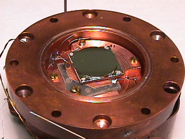
Fridge finally together and working with no leaks! We have also finished the development of a new design to hold the sapphire disk. The base post now has a small chuck opened by an 0-80 expander screw. This chuck clamps around a small sapphire puck glued to the center of the sapphire disk. This eliminates cracking problems with the sapphire/copper differential thermal expansion.
Fall 2005
Evaporatior Overhaul.
Summer 2006
Continued difficulty with low resonator Q. We suspect gap contact due to dust particles.
Summer 2007
We have developed a proceedure to unambiguously determine the presence of a bridge across the gap. We now know that there are dirt issues.
Summer 2008
The clean room area has been completely overhauled and dust collecion rates in and out of the clean area have been measured to be within specs. We have also improved the flatness of the electrode plate grinding process, and the overall assembly proceedure, as documented below.
Fall 2009
After several more attempts, we successfully assembled a reonator that passed the "gap-not-bridged tast, but only after swiping the gap with a small sheet kapton film -- a mechanical cleaning after the fact. Both the LN2 and LHe gap-fill test confirmed the absence of a bridge. This resonator had the highest third sound Q yet achieved (Q~17000) which would have been high enough to look for the stimulated condensation effect, but we have discovered two further problems: (1) there is an anomolously low critical velocity, and (2) the resonator sensitivity seems to be ~5x smaller than theoretical. This combination results in a small signal to noise ratio that prohibits our test of the gain effect.
Summer 2010
We continue to study the sensitivity discrepancy and possible causes of the low critical velocity
Circular Third Sound Modes Mathcad or PDF
Transducer Coupling Mathcad or PDF
Tunnel Diode - PLL Detection Mathcad or PDF
Inductance-Capacitance chart GIF
CW Scans and Free Decays Mathcad or PDF
Complete Mode Calculator for cavity cell resonator Mathcad
Mode Calculator modified for the stimulated condensation resonator (Mathcad 13 worksheet) or PDF
Mechanical mode Mathcad worksheet:Mathcad 14 worksheet) or PDF)
Derivation of viscous loss in an oscillating gas-filled gap PDF